
Polytetrafluoroethylene for CNC Routers
Table of Contents
What Is Polytetrafluoroethylene (PTFE)?
What Does PTFE Stand For?
PTFE, short for polytetrafluoroethylene, is a synthetic fluoropolymer produced by polymerizing tetrafluoroethylene. Its structure consists of carbon and fluorine atoms joined by strong carbon-fluorine bonds.
This structure gives PTFE its resistance to chemicals, moisture, heat, and electrical current, along with extremely low friction and low surface adhesion.
Is PTFE the Same as Teflon?
PTFE is the generic name of the polymer, while Teflon is a trademark for certain fluoropolymer products. Although Teflon is often used informally to mean PTFE, the terms are not interchangeable in every context.
When selecting material for an industrial part, verify the resin type, grade, fillers, certifications, and manufacturer specifications rather than relying on the brand name alone.
Why PTFE Is Used for Industrial Components
PTFE is used when components need chemical resistance, low friction, electrical insulation, or performance across demanding temperatures. Its very low moisture absorption also makes it suitable for wet environments.
Typical applications include seals, gaskets, valve seats, insulators, liners, guides, bushings, and custom parts for chemical, semiconductor, pharmaceutical, electrical, and food-processing equipment.
Key Properties of PTFE for CNC Machining
Exceptional Chemical Resistance
PTFE resists many acids, bases, solvents, and other aggressive chemicals, making it suitable for parts exposed to corrosive fluids or chemically demanding processes.
Actual compatibility depends on temperature, concentration, pressure, exposure time, and PTFE grade, so confirm it against the material supplier’s technical data.
High- and Low-Temperature Performance
PTFE retains useful properties over a broader temperature range than many general-purpose plastics, making it a candidate for heated systems, cold environments, laboratory equipment, and industrial fluid-handling systems.
Allowable service temperature depends on grade, load, dimensions, exposure duration, and surrounding chemicals. Published temperature ratings are not universal design limits.
Extremely Low Friction and Non-Stick Behavior
PTFE has one of the lowest coefficients of friction among commonly used solid materials. Parts can slide against mating surfaces with little resistance, reducing sticking and, in suitable applications, the need for external lubrication.
That same low friction can complicate machining: PTFE may shift in a fixture unless clamping force is even and secure.
Electrical Insulation and Low Moisture Absorption
PTFE provides strong electrical insulation and absorbs very little moisture, making it suitable for insulators, connectors, cable components, high-frequency parts, and other applications requiring stable electrical performance.
Its low moisture absorption also supports use in humid, wet, or frequently cleaned environments. Dimensional changes from temperature and mechanical loading still need to be considered.
Softness, Creep, and Limited Dimensional Stability
Compared with engineering plastics such as POM or PEEK, unfilled PTFE is relatively soft and can gradually deform under sustained pressure, a behavior known as creep or cold flow.
Excessive clamping force can distort the workpiece during machining. Once released, the part may recover toward its original shape, leaving final dimensions different from measurements taken while clamped.
Common Applications of CNC-Machined PTFE
Seals, Gaskets, and Valve Seats
PTFE is widely used for seals, gaskets, and valve seats because it combines chemical resistance with low friction. CNC routing can be used to produce profiles, holes, slots, and custom geometries from sheet or plate stock.
Designers should account for creep, sealing pressure, surface finish, and operating temperature. Filled or modified PTFE may be preferable when greater wear resistance or dimensional stability is needed.
Chemical- and Fluid-Handling Components
PTFE components are used in pumps, valves, piping systems, laboratory equipment, and chemical-processing machinery. Common parts include liners, spacers, diaphragms, seats, guides, and corrosion-resistant barriers.
Select the grade based on the fluid, temperature, pressure, purity requirements, and expected service life.
Semiconductor and Electronics Equipment
PTFE is used in semiconductor and electronics equipment for electrical insulation, chemical handling, low-friction movement, and separation of sensitive components. High-purity grades are available where contamination control is important.
Machining should minimize contamination from tools, fixtures, coolants, and surrounding materials. Critical applications may also require traceability and supplier documentation.
Pharmaceutical and Food-Processing Parts
PTFE may be used in pharmaceutical and food-processing equipment for its non-stick surface, low moisture absorption, and resistance to many cleaning chemicals. Applications include gaskets, guides, seals, liners, and other equipment components.
The PTFE designation alone does not establish regulatory suitability. Confirm that the specific grade, colorants, fillers, and manufacturing documentation meet the requirements of the intended application.
Bearings, Bushings, Liners, and Sliding Components
PTFE’s low-friction surface makes it useful for bearings, bushings, liners, slide plates, and other components involving relative movement. Filled grades are often considered for repeated contact or mechanical loading.
PTFE is not the best choice for every wear application. Consider load, speed, temperature, mating material, lubrication, alignment, and allowable deformation when selecting the material.
Can PTFE Be Machined with a CNC Router?
PTFE Parts Suitable for CNC Routing
PTFE can be machined with a CNC router, especially when supplied as sheet or plate stock. Suitable parts include gaskets, flat seals, liners, covers, spacers, insulators, guides, and other two-dimensional or shallow three-dimensional profiles.
CNC routing is particularly useful when multiple parts can be nested on a sheet or when the workpiece is too large for a smaller machining platform.
Shapes and Features That Can Be Machined
A CNC router can cut external profiles, internal openings, holes, pockets, slots, grooves, and selected three-dimensional surfaces. Practical limits depend on material thickness, cutter reach, machine rigidity, workholding, and tolerance requirements.
Deep cavities, thin walls, narrow ribs, and small unsupported features require extra care because PTFE can flex or deform as material is removed.
When CNC Routing Is More Practical Than Molding
CNC routing requires no mold, making it suitable for prototypes, replacement parts, custom components, and small- to medium-volume production. Design changes can often be made by updating the machining program.
Molding may be more economical at very high volumes, while CNC routing offers greater flexibility when quantities, dimensions, or specifications change frequently.
Main Challenges in CNC Routing PTFE
Material Movement and Deformation During Cutting
PTFE is softer and more flexible than many rigid engineering plastics. Cutting forces can deflect the workpiece, especially with thin sheets, narrow strips, small parts, or features far from a fixture point.
Stable support, light passes, sharp tools, and balanced workholding help control movement. Fixtures should restrain the material without compressing or distorting it.
Burrs, Smearing, and Poor Edge Quality
Dull tools can rub against PTFE instead of cutting it cleanly, causing burrs, stringy chips, smeared edges, and inconsistent surface finishes.
Sharp cutting edges, suitable rake geometry, effective chip removal, and a separate finishing pass can improve results. Tool condition should be monitored during repeat production.
Heat Buildup and Dimensional Changes
Although PTFE performs at elevated service temperatures, localized frictional heat can still affect machining. It can soften the cutting zone, promote smearing, and make dimensional control more difficult.
Machining conditions should favor cutting over rubbing. Adjusting spindle speed, feed rate, flute count, depth of cut, and chip evacuation can help keep the cutting zone stable.
Difficulty Holding Tight Tolerances
PTFE can deform under cutting, clamping, and inspection forces. Thermal expansion and creep can also affect dimensions immediately after machining.
Critical parts may require staged machining, stabilization time, controlled inspection conditions, or separate roughing and finishing operations. Tolerances should reflect functional requirements rather than assumptions based on metal parts.
Workholding Challenges Caused by PTFE’s Low Friction
PTFE’s slippery surface can allow the workpiece to shift during machining. Simply increasing clamp pressure may deform the material.
Fixtures that distribute holding force over a broad area are generally preferable. Vacuum tables, custom nests, perimeter restraints, tabs, and light mechanical clamping can be combined as needed.
How to Machine PTFE with a CNC Router
Use Sharp, High-Rake Cutting Tools
PTFE is best machined with sharp tools that shear the material cleanly. Positive- or high-rake geometry can reduce cutting pressure and limit deformation around the cut.
Carbide tools are commonly used for repeat production because they retain a sharp edge longer than many general-purpose tools. The best geometry depends on the operation and PTFE grade.
Select an Appropriate Flute Count and Tool Geometry
Low-flute-count tools provide more room for chip evacuation and can reduce rubbing. Single-flute cutters may work well for some routing operations, while other features or finishing requirements may call for different geometry.
Upcut tools improve chip removal but may lift thin material. Downcut tools can hold the surface down but may trap chips. Match the cutting direction to the fixture and part geometry.
Balance Spindle Speed, Feed Rate, and Chip Load
PTFE machining requires the right balance of spindle speed and feed rate. High spindle speed with a slow feed can generate heat, while an overly aggressive feed can increase deflection and part movement.
Start with conservative settings based on the tool supplier’s guidance, then make a test cut. Check chip shape, edge quality, cutting sound, tool load, and dimensions before increasing production speed.
Use Shallow Passes to Reduce Cutting Pressure
Multiple shallow passes can reduce cutting force and workpiece deflection, especially with thin sections, detailed profiles, unsupported features, and parts requiring consistent dimensions.
The final pass should remove a small, controlled amount of material with a sharp tool. Too little material can cause rubbing, while too much can deflect the part during finishing.
Maintain Reliable Chip Evacuation
PTFE can produce continuous or stringy chips that remain near the cutter. Recutting them can increase heat, mark the surface, or interfere with the toolpath.
Airflow, extraction, and suitable flute geometry can help clear the cutting zone. Chip removal should not lift small parts or contaminate high-purity components.
Perform Test Cuts Before Production
A test cut helps verify the combination of PTFE grade, stock thickness, tool, spindle speed, feed rate, fixture, and toolpath. Settings that work for one grade may not perform the same way with another.
Measure the test part after removing it from the fixture and allowing it to stabilize. This can reveal dimensional changes that are not apparent while the material is clamped.
Workholding Methods for PTFE Sheets and Parts
Vacuum Table Workholding
A vacuum table distributes holding force across a broad surface area, making it well suited for PTFE sheet and plate. Zoned vacuum control can focus suction around the active machining area.
Holding force must remain sufficient as profiles are cut and the effective vacuum area decreases. Gaskets, masking, tabs, or an onion-skin pass may be needed to prevent movement near the end of the cycle.
Mechanical Clamps and Custom Fixtures
Mechanical clamps provide positive restraint but must be used carefully. Excessive force can compress PTFE and cause dimensional changes after the part is released.
Custom nests, soft jaws, perimeter stops, and broad clamping surfaces can distribute pressure more evenly. Fixtures should support the workpiece close to critical features.
Tabs, Spoilboards, and Sacrificial Layers
Tabs can keep individual parts attached to the surrounding sheet during profile cutting, while a spoilboard supports through-cuts and protects the machine table.
A thin layer of material can also be left during the first operation and removed in a final pass. The selected method should account for any additional deburring or finishing required.
How to Prevent Thin PTFE Sheets from Lifting or Shifting
Thin PTFE sheets can lift, flutter, or slide when cutting forces exceed the available holding force. A flat spoilboard, distributed vacuum, edge restraint, and suitable tool direction can improve stability.
Toolpaths should avoid releasing small parts too early. Machining internal features before external profiles usually preserves more holding area.
How to Reduce Burrs and Improve Surface Finish
Prevent Tool Rubbing and Material Smearing
Rubbing can result from dull tools, insufficient feed per tooth, poor chip evacuation, or unsuitable tool geometry. The resulting heat can leave smeared or rounded edges.
A sharp cutter should shear the material cleanly and produce recognizable chips. Changes in chip form, cutting sound, or edge appearance can indicate tool wear or unsuitable cutting conditions.
Add a Light Finishing Pass
A dedicated finishing pass can improve dimensional consistency and edge quality by removing a controlled amount of material with a sharp tool and stable toolpath.
Climb and conventional cutting may produce different results depending on the machine, fixture, and feature. Both can be evaluated during test cuts before production settings are finalized.
Deburring and Secondary Finishing Methods
Even with optimized machining, PTFE parts may require manual deburring. A sharp blade, purpose-built deburring tool, or other controlled method can remove thin burrs without tearing the edge.
Aggressive sanding can round critical features or alter dimensions, so finishing methods should match the part’s sealing, sliding, assembly, and cosmetic requirements.
Inspecting Dimensions After Machining
Inspect PTFE after releasing it from the fixture. Measurements taken while the part is compressed may not reflect elastic recovery or deformation.
For precision components, control inspection force, room temperature, stabilization time, and measurement location. Functional gauges may be useful when contact measurement could deform the part.
Advantages of CNC Routing PTFE
No Mold or Dedicated Production Tooling Required
CNC routing produces parts directly from sheet or plate stock without a production mold, reducing the initial tooling commitment for custom components, prototypes, replacement parts, and limited-volume orders.
Fixtures may still be required, but they can often be modified or replaced more easily than molds when designs change.
Efficient Production of Custom Profiles and Flat Parts
A CNC router can machine external profiles, openings, pockets, grooves, and hole patterns in one programmed workflow, making it well suited for flat seals, gaskets, liners, spacers, and insulators.
Nesting multiple parts on a sheet can improve material utilization, provided enough spacing and holding area are maintained between them.
Consistent Quality for Repeat Production
Once the toolpath, fixture, and cutting conditions are validated, a CNC router can reproduce the same geometry across repeated production cycles.
Consistency still depends on tool condition, material variation, machine calibration, fixture cleanliness, and inspection. Documented processes help maintain quality over time.
Flexible Prototyping and Small- to Medium-Batch Manufacturing
Machining programs can be updated when dimensions, hole locations, or profiles change, making CNC routing useful during product development or for multiple part variations.
It also supports production volumes that may not justify molding while offering greater repeatability than manual fabrication.
Efficient Machining of Large PTFE Sheets
Large-format CNC routers can accommodate parts that may not fit on smaller machines and can produce multiple components from a single sheet in one setup.
The machine still needs sufficient table flatness, vacuum capacity, positioning accuracy, and support across the full working area.
How to Select the Right PTFE Grade
Virgin PTFE
Virgin PTFE contains no reinforcing fillers and offers the material’s characteristic chemical resistance, electrical insulation, low friction, and high purity.
However, it may lack the wear resistance, creep resistance, or dimensional stability needed for heavily loaded components. Review the application requirements before selecting an unfilled grade.
Modified PTFE
Modified PTFE contains a small amount of comonomer or another controlled modification designed to improve selected properties while retaining the main benefits of PTFE.
Depending on the product, modified grades may improve deformation resistance, surface quality, or permeability. Confirm specific performance benefits with supplier data.
Glass-Filled PTFE
Glass-filled PTFE is used when greater wear resistance, stiffness, or creep resistance is needed, including for bearings, guides, seals, and mechanically loaded parts.
The filler affects machinability, surface behavior, chemical compatibility, and electrical performance. Glass-filled PTFE may also increase tool wear compared with virgin PTFE.
Carbon- and Graphite-Filled PTFE
Carbon or graphite fillers can improve wear resistance, deformation resistance, thermal conductivity, or sliding performance, depending on the formulation.
These grades are often considered for dynamic components, but fillers can also affect electrical properties and chemical compatibility. Select the grade based on the operating environment.
Bronze-Filled PTFE
Bronze-filled PTFE can improve compressive strength, wear resistance, thermal conductivity, and dimensional stability in selected mechanical applications.
However, metallic fillers may not be suitable for corrosive environments or applications requiring electrical insulation. Evaluate chemical exposure and electrical requirements before selection.
Expanded PTFE
Expanded PTFE (ePTFE) has a porous structure and is commonly used for sealing, filtration, insulation, and membrane applications.
Its structure and mechanical behavior differ from those of solid PTFE, so machining, cutting, and workholding methods should be developed for the specific ePTFE product.
Food, Medical, and High-Purity Grade Requirements
Food-contact, medical, pharmaceutical, and semiconductor applications may require specific certifications, declarations, traceability, cleanliness, or testing.
The PTFE designation alone does not establish compliance. Verify documentation for the specific grade and confirm that machining and cleaning processes do not compromise its intended suitability.
PTFE vs. Other Engineering Plastics for CNC Routing
PTFE vs. UHMW-PE
Both PTFE and UHMW-PE offer low friction and low moisture absorption. UHMW-PE is often selected for abrasion resistance and impact performance, while PTFE is generally better suited to more demanding chemical or temperature conditions.
UHMW-PE may be more economical for wear strips, guides, and material-handling components. PTFE may be preferable when chemical resistance, electrical performance, or temperature capability is the priority.
PTFE vs. POM
POM, or acetal, offers greater stiffness and dimensional stability than virgin PTFE and is widely used for gears, rollers, bushings, and precision mechanical parts.
PTFE generally offers lower friction and broader chemical resistance, while POM may be easier to machine accurately when rigidity and tight tolerances are more important.
PTFE vs. PEEK
PEEK combines high-temperature capability with greater strength, stiffness, and dimensional stability, making it suitable for heavily loaded, precision, structural, and other high-performance parts.
PTFE offers lower friction and may provide advantages in chemical, sealing, and electrical applications. PEEK is typically selected when its higher mechanical performance justifies the added material cost.
When PTFE Is a Strong Material Choice
PTFE is a strong candidate when a component requires low friction, non-stick behavior, electrical insulation, low moisture absorption, or resistance to aggressive chemicals.
Common applications include seals, gaskets, liners, insulators, fluid-handling parts, and lightly loaded sliding components where its softness can be accommodated.
When Another Engineering Plastic May Be More Suitable
Another material may be preferable when the part requires greater rigidity, strong thread retention, heavy mechanical loading, high abrasion resistance, easy adhesive bonding, or very tight dimensional tolerances.
Compare materials based on overall functional requirements rather than individual properties. Temperature, load, chemical exposure, wear, tolerances, compliance, production volume, and cost all influence the decision.
Safety and Environmental Considerations
Avoid Excessive Heat During PTFE Machining
PTFE should not be exposed to uncontrolled overheating, as excessive temperatures can degrade the polymer and generate hazardous decomposition products.
Use appropriate cutting conditions, ventilation, chip control, and workplace procedures. Operators should follow the material supplier’s safety data sheet and applicable occupational safety requirements.
PTFE, PFOA, and PFAS: Understanding the Difference
PTFE is a fluoropolymer, while PFOA is a different fluorinated substance historically used as a processing aid in some fluoropolymer manufacturing. PTFE and PFOA are not synonymous.
PTFE may fall within broad definitions of PFAS because of its fluorinated structure. Safety and environmental discussions should distinguish the finished polymer from processing aids, impurities, manufacturing emissions, and thermal decomposition products.
Handling and Disposing of PTFE Chips and Scrap
Collect machining chips to prevent contamination, workplace buildup, and uncontrolled release. Clean, separated scrap may also be easier to evaluate for recycling or specialized recovery than mixed waste.
Disposal requirements vary by location and waste condition. PTFE scrap should not be burned in uncontrolled conditions, and facilities should follow supplier guidance and applicable local regulations.
How to Choose a CNC Router for PTFE Machining
Machine Rigidity and Motion Accuracy
A rigid machine and accurate motion system help maintain a consistent toolpath. Although PTFE is relatively soft, vibration and positioning errors can still affect dimensions and edge quality.
Rigidity becomes especially important for large parts, thin features, multiple parts per sheet, and applications requiring repeatable tolerances.
Vacuum Table and Fixturing Capability
A CNC router for PTFE should support workholding methods that distribute force without excessive compression. Zoned vacuum tables are particularly useful for sheet and plate.
The machine should also accommodate custom fixtures, stops, clamps, tabs, and spoilboards when vacuum alone cannot hold the part securely.
Spindle Control and Low-Runout Performance
Stable spindle control helps balance cutting speed, feed rate, and chip load, while low runout keeps the cutting edges engaged consistently.
Because PTFE machines best with sharp tools and clean shearing, excessive runout can cause uneven tool wear, rubbing, burrs, and dimensional variation.
Tool-Changing and Multi-Process Capability
An automatic tool changer can support roughing, finishing, drilling, chamfering, and other operations without manual tool changes.
This can improve repeatability and reduce handling when a part requires multiple tools or several part types are produced in one workflow.
Chip Collection and Workplace Cleanliness
Uncontrolled PTFE chips can collect around the cutter or spread across the work area. Effective extraction and airflow help maintain cutting quality and workplace cleanliness.
For high-purity applications, the collection system should also minimize cross-contamination from materials previously machined on the same equipment.
Matching the Machine to Part Size and Production Volume
The right CNC router depends on stock dimensions, part thickness, tolerances, feature complexity, batch size, and production frequency.
Evaluate the entire process, including loading, workholding, tool changes, cutting time, chip collection, deburring, inspection, and material utilization.
Frequently Asked Questions About CNC Machining PTFE
Is PTFE Easy to Machine?
PTFE is relatively easy to cut because it is soft, but producing accurate, burr-free parts can be challenging. Its flexibility, creep, thermal expansion, and low-friction surface require careful process control.
Good results depend on sharp tools, low cutting pressure, stable support, controlled clamping, effective chip evacuation, and realistic tolerances.
Can a CNC Router Cut Teflon Sheets?
Yes. A CNC router can cut PTFE sheets into gaskets, seals, liners, spacers, insulators, and custom profiles, as well as machine holes, slots, pockets, and selected three-dimensional features.
The machine and fixture must match the sheet size, thickness, part geometry, and required accuracy. Test cuts are recommended before production.
What Cutting Tool Is Best for PTFE?
A sharp carbide cutter with positive rake geometry is a common choice for PTFE. Low-flute-count tools provide more room for chip evacuation and can reduce heat from recutting chips.
The best tool depends on the operation, including profiling, pocketing, drilling, roughing, and finishing. Use the tool manufacturer’s guidance as a starting point.
How Can Burrs Be Reduced When Machining PTFE?
Reduce burrs by using a sharp tool, preventing rubbing, clearing chips effectively, supporting the workpiece, and using a controlled finishing pass.
Check tool wear when burrs or smearing increase. Any remaining burrs can be removed carefully with an appropriate manual finishing method.
Can PTFE Parts Hold Tight Tolerances?
PTFE can be machined to controlled dimensions, but it does not behave like metal or rigid engineering plastics. Clamping force, inspection force, temperature, and creep can all affect measured dimensions.
Tight-tolerance parts may require staged machining, stabilization time, controlled inspection, or a filled or modified PTFE grade with better dimensional stability.
Does PTFE Require Coolant During Machining?
PTFE is often machined dry with effective chip evacuation or directed air, but the appropriate method depends on the operation, equipment, tool, finish requirements, and contamination limits.
If coolant or lubricant is used, verify its compatibility and effect on cleanliness. High-purity, food, medical, and pharmaceutical applications may have additional restrictions.
What Is the Difference Between Virgin and Filled PTFE?
Virgin PTFE contains no reinforcing fillers and offers chemical resistance, electrical insulation, low friction, and high purity. Filled PTFE uses materials such as glass, carbon, graphite, or bronze to modify specific properties.
Fillers can improve wear resistance, stiffness, thermal conductivity, or creep resistance but may reduce other properties. Select the formulation based on the component’s operating conditions.
Choosing the Right CNC Router for PTFE Parts
PTFE is well suited for components requiring chemical resistance, low friction, electrical insulation, low moisture absorption, or performance across demanding temperatures. CNC routers can machine PTFE effectively, especially from sheet or plate stock.
Consistent results depend on more than cutting the material to shape. Workholding, tool sharpness, cutting pressure, chip evacuation, heat control, finishing, inspection, and grade selection all affect the finished part.
When choosing a CNC router, consider the complete process, including part size, tolerances, material grade, fixturing, and production volume. Stable motion, flexible workholding, precise spindle control, and effective chip management can improve consistency and production efficiency.
This media is sponsored by The SHODA Company
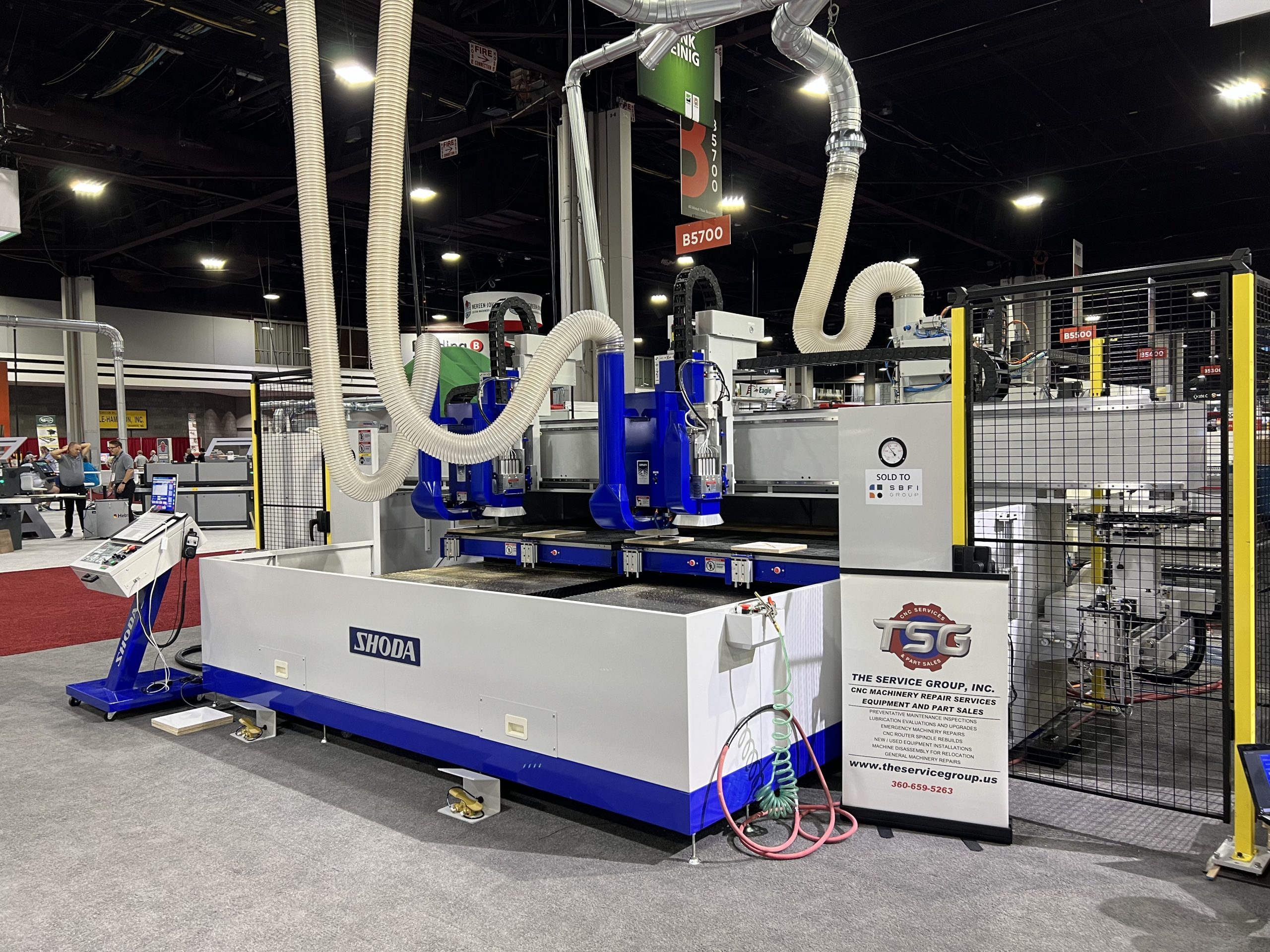
A Pioneer in Japanese CNC Router Technology
SHODA has been in business since 1926 and was the first company in Japan to develop an NC router. With a long history of precision machining, the company’s CNC routers are used to process a variety of materials—such as plastics, resins, and lightweight metals—with proven accuracy and reliability.
In 2014, SHODA developed a new type of NC router that doesn’t produce cutting dust. In many manufacturing environments, dust from machining can pose serious health risks if inhaled over long periods. SHODA’s solution to this issue has gained attention worldwide and is now used across the U.S., Europe, and Asia.