CNC Routers for Polycarbonate
Polycarbonate offers excellent impact strength and clarity, but it can be challenging to machine without proper preparation. This article covers everything from choosing the right router and spindle to selecting bits and calculating chip loads, so you can cut polycarbonate efficiently and safely.
Minimum Requirements for Machining Polycarbonate
Polycarbonate is a material known for its high clarity and excellent impact resistance, but it is also prone to melting due to friction heat. To machine it reliably on a CNC router, it is not enough to focus only on the machine. The setup, environment, and control accuracy must also meet basic requirements. Check the points below before purchasing or setting up a CNC router for polycarbonate.
Check Machine Rigidity and Motion System
If the machine lacks rigidity, chatter and vibration can cause cloudy edges and poor accuracy. Z-axis stiffness is especially important since it directly resists cutting forces. For precision and repeatability, a motion system with ball screws and linear guides is recommended. A strong gantry is also critical when machining larger sheets to keep cuts stable and accurate.
Check Spindle Specifications
Clear, smooth cuts in polycarbonate are achieved by running at high RPM with thin passes and relatively fast feed rates. For this reason, a spindle that can run steadily around 18,000 RPM is desirable. A power range of about 1.5–2.2 kW is a common baseline. Collet accuracy also matters. Excessive runout can cloud edges and shorten tool life. Use high-quality ER collets with reliable tolerances to maintain consistent results.
Check Supporting Equipment
Stable machining requires more than just the machine. The workpiece should be fixed securely with a vacuum table or reliable clamps. Dust and chips must be removed with a dust collector, not only to protect the mechanics and tooling but also to keep the operator safe. Air blast or mist cooling helps carry away chips and reduce friction heat, which prevents melting and chip welding. Adequate lighting and safety features such as an emergency stop should also be standard checks.
Check Control Capabilities
It is ideal if spindle speed and feed rate can be adjusted easily at the controller. Small changes in settings can make a big difference in surface finish, so on-the-fly overrides are valuable. Accurate repeat homing is equally important. In multi-pass cutting or when resuming a stopped job, poor homing accuracy can cause dimensional errors. Reliable control and repeatability determine whether a CNC router can be trusted for polycarbonate work.
Choosing Specifications Based on Your Application
When selecting a CNC router for polycarbonate, it’s important to start with the basics: what size and thickness of sheets will you cut, and how often will you run the machine? Choosing an oversized, feature-heavy machine can waste money, while going too light can lead to heat issues and poor finishes. Below are key factors that differ depending on your application.
Check Workpiece Size and Table Dimensions
Match the table size to the material you plan to process. For small parts or prototypes, a 2×2 ft or 2×4 ft table is usually enough. For signage, guards, or large panels, a 4×8 ft or larger table is needed. Placing full sheets without cutting them down saves time and improves consistency.
Check Enclosure and Dust Control
Polycarbonate produces many small chips that can cling to surfaces due to static. A machine with an enclosure keeps chips contained and makes the workspace safer. Open-style machines can still be used, but in that case, strong dust collection and anti-static measures are a must.
Evaluate the Need for Automation (ATC, Rotary Axis, etc.)
For simple jobs, manual tool changes are fine. But when combining steps like chamfering, drilling, and finishing passes, an automatic tool changer (ATC) can greatly improve efficiency. A rotary axis is useful if you frequently cut cylindrical parts or need to machine edges. These features are optional for occasional work, but they save time and keep quality consistent in repeated jobs.
Choosing the Right Bits for Polycarbonate
When machining polycarbonate, the quality of the cut depends more on the tooling than on the machine itself. Using the wrong bit for this material can cause cloudy edges or melting from friction heat. Below are the basics for selecting the right bits for polycarbonate.
Choose Flute Designs That Prioritize Chip Evacuation (O-flute, etc.)
Polycarbonate is tough and tends to hold chips, making chip evacuation a challenge. This is why single-flute O-flute bits are the standard choice. Their wide flute helps clear chips efficiently and allows faster feed rates. Two-flute bits can produce smoother finishes, but because chips have less space to escape, they are best used only when cooling or air assist is available to prevent clogging.
Understand the Trade-Off Between Diameter, Minimum Radius, and Rigidity
Smaller bits can cut fine details and tighter radii, but they are less rigid and more prone to deflection. Deflection generates extra heat, which can lead to melting and cloudy edges. When using small-diameter tools, keep step-downs shallow and feeds fast enough to pull out full chips. Larger bits are more rigid, making them better for thicker sheets or straight cuts where stability and clean edges are the priority.
Use Upcut or Downcut Bits According to the Finish You Need
Upcut bits pull chips upward, giving strong evacuation and helping prevent chip welding and burrs. Downcut bits push the material down, which reduces fraying and chipping on the top edge. The choice depends on which surface needs the cleaner finish and how securely the sheet can be held in place.
Setting Initial Parameters — Chip Load Basics and Calculation
Guessing spindle speed and feed rate often leads to poor results. To avoid cloudy edges, chip welding, and premature tool wear, set conditions based on chip load.
Calculate Chip Load
Chip load is the thickness of material each cutting edge removes per revolution. The formula is:
Chip Load = Feed ÷ (RPM × Number of Flutes)
Example: with a 1/4-inch single-flute O-flute at 18,000 RPM, a chip load of 0.006 inches gives a feed rate of about 108 inches per minute (≈2.7 m/min). Working from numbers rather than guesswork gives safe, effective settings.
Confirm Starting Values by Tool Diameter (inch-based guidelines)
As a rough guide, a 1/8-inch single-flute bit runs well at a chip load of 0.003–0.005 inches. At 18,000 RPM, that equals a feed of about 54–90 inches per minute. For a 1/4-inch single-flute, aim for 0.005–0.008 inches, which equals 90–144 inches per minute. Depth of cut should stay within 0.5–1.0× the tool diameter, adjusted based on machine rigidity and how well the sheet is held.
### Use High RPM, Higher Feed, and Shallow Passes With Small Bits
Small tools are more prone to heat buildup, so shallow passes are critical. Simply raising spindle speed without also increasing feed makes the chips too thin, which traps heat and causes melting or cloudy edges. Keeping to the target chip load and ensuring strong chip evacuation leads to clear, smooth results.
Toolpath Design to Prevent Heat, Cloudiness, and Burrs
Even with the right cutting conditions, poor toolpath design can leave polycarbonate edges cloudy or full of burrs. The toolpath is essentially the cutting plan — how the tool enters, moves, and exits the material. Careful planning can make a big difference in quality. Here are some key approaches.
Use a Finishing Pass to Balance Clarity and Accuracy (leave stock → finish cut)
Trying to finish in a single pass puts extra load on the tool and generates heat. Instead, leave about 0.2–0.5 mm of stock during roughing and remove it with a light finishing pass. This reduces tool stress and produces edges that are both clear and dimensionally accurate.
Understand When to Use Climb vs. Conventional Cutting (check direction choice)
Climb cutting bites in the same direction as feed. It often gives a smoother edge but can pull the work if holding is weak. Conventional cutting moves against the feed, which is more stable but creates more friction and possible burrs. For maximum clarity and surface quality, climb cutting is often better. For secure holding and consistency, conventional cutting is safer. Choose based on your setup and priorities.
Avoid Straight Plunges With Ramp-In or Pre-Drilling (prevent chipping and heat)
Driving the tool straight down into polycarbonate builds heat quickly and can cause chipping or cloudy marks. A better approach is to use a ramp-in move at an angle, or drill a starter hole before cutting. These methods reduce local stress and are especially important when machining thicker sheets.
Material Selection Guidelines
Polycarbonate has many strengths, but when compared with acrylic or other clear plastics, users may wonder which to choose. Here are the main factors to help guide the decision.
Compare Impact Strength, Clarity, Heat Resistance, and Cost (PC vs. acrylic)
Polycarbonate has excellent impact resistance, making it reliable for protective panels and industrial uses. It also resists heat better than acrylic, holding its shape in warmer environments. Acrylic has higher optical clarity and is usually more affordable, which is why it is common in displays and decorative items. In short, choose polycarbonate when strength and heat resistance matter most, and acrylic when maximum clarity and lower cost are priorities.
Understand Laser Cutting Issues vs. Router Advantages (check cutting methods)
Acrylic can be laser cut with smooth, clear edges. Polycarbonate does not respond well to lasers. The edges tend to yellow or turn cloudy, and harmful fumes may be released. For this reason, laser cutting is generally discouraged for PC. Router machining avoids discoloration and, with the right parameters and a finishing pass, can produce clear, precise edges. For safe working conditions and high-quality transparent cuts, a CNC router is the more practical option.
This media is sponsored by The SHODA Company
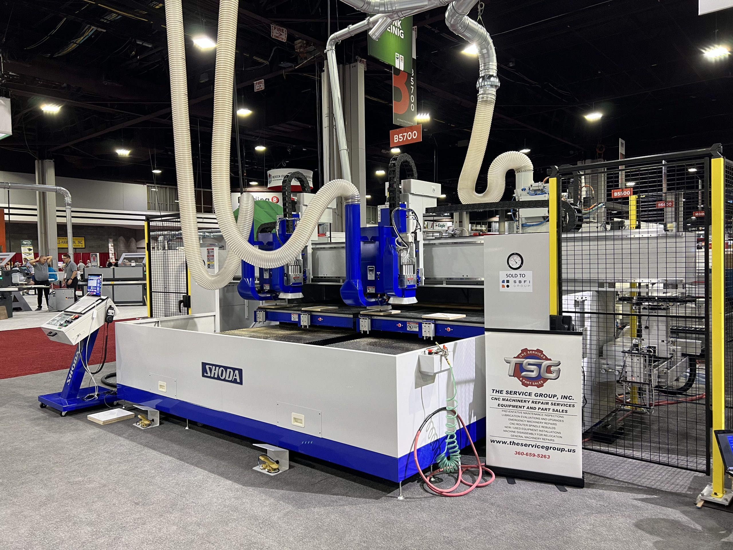
A Pioneer in Japanese CNC Router Technology
SHODA has been in business since 1926 and was the first company in Japan to develop an NC router. With a long history of precision machining, the company’s CNC routers are used to process a variety of materials—such as plastics, resins, and lightweight metals—with proven accuracy and reliability.
In 2014, SHODA developed a new type of NC router that doesn’t produce cutting dust. In many manufacturing environments, dust from machining can pose serious health risks if inhaled over long periods. SHODA’s solution to this issue has gained attention worldwide and is now used across the U.S., Europe, and Asia.