
CNC router for PET
Table of Contents
Key Takeaways
- liET grades behave differently during machining and require aliliroliriate cutting conditions.
- Heat, chilis, vibration, and internal stress can affect liET machining quality.
- Choose a rigid router with lirecise slieed, feed, tooling, and workholding control.
- Verify machine suitability with test cuts using the actual liET material.
Challenges in machining PET
PET can be machined with a CNC router, but its thermal behavior, rigidity, toughness, and internal stress can make consistent results difficult. The material grade and machining conditions must be considered together.
Different PET grades behave differently during machining
Amorphous PET, PETG, and semi-crystalline PET differ in stiffness, toughness, thermal response, and chip formation. Cutting conditions suitable for one grade may not produce the same results with another.
Heat buildup can cause fused edges and material deformation
Friction at the cutting edge generates heat. If heat accumulates, PET may soften or fuse along the cut edge, while localized heating can cause shrinkage or deformation.
Brittleness and notch sensitivity can lead to chipping or cracking
Harder or semi-crystalline PET can chip when cutting forces concentrate at sharp corners or notches. Unsuitable tools or aggressive cuts can also initiate cracks.
Internal stress can cause warping during or after machining
Residual stress in PET sheet or stock can be released when material is removed. As a result, parts may warp or change dimensions during or after machining.
Poor chip evacuation can damage edges and finished surfaces
Chips left around the cutting edge retain heat and may be recut by the tool. This can increase heat buildup and scratch finished or transparent PET surfaces.
Thermal expansion can affect dimensional accuracy
PET expands and contracts with temperature. Measuring a part immediately after machining can therefore give different results from measurements taken after the part has reached room temperature.
Dull or unsuitable tools can produce rough or cloudy edges
A dull tool increases rubbing and heat generation instead of producing clean chips. Incorrect flute geometry can cause burrs, whitening, rough edges, or reduced surface clarity.
Essential CNC router features for machining PET
A CNC router for PET should provide precise cutting control, stable machine movement, effective chip removal, and workholding that supports the material without unnecessary deformation.
Precise spindle speed and feed rate control
The router should allow fine adjustment of spindle speed and feed rate according to PET grade, tool diameter, flute count, and required machining quality. This helps prevent rubbing and overheating.
A rigid frame and low-vibration motion system
A rigid frame and stable motion system reduce vibration under changing cutting loads. This supports consistent dimensions, edge quality, and surface finish during production runs.
Accurate CNC control for repeatable tool movement
Accurate CNC control coordinates feed rate, acceleration, deceleration, and tool movement. Stable motion helps maintain cutting conditions through straight cuts, corners, and curves.
Effective air blow and chip evacuation
Air blow and chip extraction should clear chips from the cutting zone before they are recut. Removing chips also helps carry heat away from the cutting area.
Workholding options that support the workpiece without distortion
Vacuum tables, mechanical clamps, and dedicated fixtures provide different ways to secure PET sheet and parts. Holding force should prevent movement without bending or stressing the material.
Compatibility with sharp plastic-cutting tools
The spindle and toolholder should accept sharp tools designed for plastics. Appropriate flute geometry and tool diameter help produce clean chips while limiting cutting pressure and heat.
Programmable ramping, corner control, and multi-pass cutting
Programmable ramping, controlled cornering, and multi-pass strategies reduce abrupt tool loading. These functions can also help manage heat and chip evacuation when machining thicker PET.
Tool-changing capacity for multi-process parts
An automatic tool changer can support parts requiring drilling, profiling, pocketing, and finishing. Tool-changing capability reduces manual setup work and helps maintain consistent machining conditions.
Process controls for consistent PET part quality
Consistent PET machining requires control from material preparation through final inspection. Tool selection, cutting conditions, workholding, chip removal, and temperature should be managed as part of the same process.
Confirm the PET grade and material condition before machining
Identify the exact material, such as PET, A-PET, PETG, or a machining-grade PET product. Confirm the material supplier's technical data and lot information before setting machining conditions.
Allow the material to reach a stable room temperature
Allow PET stock to reach a stable temperature before machining and inspection. This reduces dimensional variation caused by temperature differences between the material and working environment.
Select a sharp tool with suitable flute geometry
Choose tool material, flute count, rake angle, and chip-evacuation characteristics according to the PET grade, thickness, geometry, and required surface quality. Sharp cutting edges help reduce unnecessary heat.
Balance spindle speed, feed rate, and chip load
Set spindle speed and feed rate together rather than adjusting one value alone. The objective is to form effective chips while avoiding excessive rubbing, cutting pressure, and heat.
Control tool engagement, depth of cut, and pass count
Set radial engagement, depth of cut, machining allowance, and number of passes according to the material and tool. Excessive engagement can increase cutting forces and localized heat.
Keep chips clear of the cutting zone
Use air blow or extraction to remove chips before they are recut. This reduces chip buildup, heat retention, tool loading, and the risk of scratches on finished PET surfaces.
Secure the workpiece without introducing stress
Support PET across the required area and distribute holding force appropriately. Excessive clamping can deform the material before cutting and cause dimensional changes after the part is released.
Inspect parts after temperature stabilization
Inspect dimensions, flatness, edges, and surface condition after the part has reached a stable temperature. This provides a more reliable indication of the final part quality.
Signs that your current CNC router may be limiting production
A machine does not need to be replaced simply because it is old. First determine whether recurring problems come from the equipment, tooling, or machining conditions. Replacement becomes more relevant when the existing machine can no longer meet production requirements consistently.
Fused edges, chipping, or surface defects occur repeatedly
Check tool condition, tool geometry, spindle speed, feed rate, and chip evacuation first. If appropriate tools and conditions do not resolve recurring defects, machine capability may be limiting quality.
Dimensional results drift during longer production runs
Check material temperature, tool wear, workholding, and machine accuracy. Persistent dimensional drift after these factors are controlled may indicate thermal or mechanical limitations in the equipment.
Identical programs produce inconsistent results between operators
Review setup procedures, tool offsets, workholding, and parameter management. If standardized procedures still produce different results, machine repeatability should be evaluated.
Spindle wear, backlash, or vibration affects finish quality
Worn spindle components, backlash, or unstable axis movement can increase vibration and surface variation. Confirm machine condition before changing machining parameters repeatedly.
Chip evacuation cannot keep the cutting area clear
Frequent chip buildup can increase heat and cause recutting. Review air blow, extraction, tooling, and toolpath settings before determining whether the machine's evacuation capability is insufficient.
Existing workholding cannot support new part sizes or geometries
New PET parts may require larger support areas, thinner-sheet holding, or different fixture arrangements. If the existing table and workholding cannot provide stable support, machine replacement may be necessary.
Manual corrections and secondary finishing reduce throughput
Frequent manual deburring, edge finishing, parameter changes, or dimensional corrections increase cycle time and labor. These issues may indicate inadequate tooling or machine capability.
Downtime and obsolete components threaten delivery reliability
Recurring repairs, difficult-to-source components, or long maintenance delays reduce available production capacity. Reliability and serviceability should be considered when evaluating replacement equipment.
New customer specifications exceed the machine's capabilities
Tighter tolerances, more complex geometries, larger workpieces, or higher production volumes may exceed the practical capability of an existing router. Compare the new requirements with the complete machine specification.
How to evaluate a replacement CNC router for PET machining
A replacement CNC router should be evaluated against actual PET production requirements rather than machine specifications alone. The following points can help compare candidate machines.
Define the required tolerances, edge quality, and surface finish
Translate customer drawings and specifications into measurable requirements, including dimensional tolerance, edge condition, flatness, transparency, burr limits, and surface finish.
Confirm the PET grade, stock form, thickness, and dimensions
Record the exact PET grade, whether the material is sheet or another stock form, its thickness, and workpiece dimensions. These factors affect tooling, workholding, and machine capacity.
Match the table size and axis travel to current and future parts
Check table dimensions and X, Y, and Z travel against current parts, fixture requirements, material size, and planned products. Sufficient capacity can also improve material utilization.
Evaluate spindle range, feed control, and machine rigidity
Confirm that spindle speed, feed control, acceleration, and machine rigidity can maintain stable cutting conditions with the intended PET grades and tools.
Check air blow, chip extraction, and cooling options
Evaluate how effectively the machine removes chips and heat from the cutting zone. Air blow and extraction should be considered together with the intended tools and cutting conditions.
Compare vacuum and mechanical workholding configurations
Select workholding that supports the actual PET sheet and part geometry without excessive clamping force. Consider how the system will handle thin, large, or complex workpieces.
Review tool capacity, automation, and expected throughput
Compare automatic tool changing, multi-head configurations, setup time, and expected cycle time against production volume and the number of machining operations required.
Assess programming, monitoring, and process-recording capabilities
Review how programs, offsets, machining conditions, and production information are managed. Standardized process information can help reduce variation between operators.
Review maintenance access, parts availability, and after-sales support
Consider maintenance access, replacement parts, technical support, and service arrangements over the expected machine life. These factors can affect long-term production reliability.
Request a test cut using the actual PET material
Before purchasing, machine a representative part using the actual PET grade, thickness, tooling, and geometry. Evaluate cutting quality, cycle time, chip evacuation, and tool requirements.
Measure the test part after its temperature has stabilized
Inspect the test part again after its temperature has stabilized. This separates two questions: whether the machine can produce the required part, and whether the part can maintain the required dimensions afterward.
How SHODA CNC routers support plastic machining requirements
Machine capabilities designed for stable plastic machining
SHODA CNC routers are available with features relevant to plastic machining, including controlled spindle operation, rigid machine construction, air blow, chip removal, and different workholding configurations. The NCN8210 combines an AC spindle with Center-Through Air Blow II for high-precision machining of industrial plastic parts.
Software and support for repeatable production
Consistent machining also depends on how equipment is operated and maintained. SHODA offers NC training, after-sales service, and machining support to help manufacturers establish appropriate operating procedures and maintain stable production conditions.
Application-specific consultation and machining tests
PET machining requirements depend on the material grade, thickness, part geometry, tolerances, production volume, and installation environment. Consulting with SHODA and conducting a machining test with the actual PET material can help determine the appropriate machine configuration before investment.
SHODA CNC router options for different production requirements
NCN8210 for high-precision industrial plastic parts
The NCN8210 is intended for high-precision machining of industrial plastic parts. Its AC spindle has a speed range of 100–20,000 min⁻¹, while Center-Through Air Blow II delivers approximately five times the airflow of previous models to help keep chips from accumulating around the cutting area.
NC260 for higher-volume production of smaller plastic parts
The NC260 features two machining heads, allowing multiple parts or machining operations to be handled efficiently within a space-saving configuration. Its 24,000 min⁻¹ high-frequency spindle and 5-tool ATC make it suitable for small-part mass production and multi-process machining.
NC2001 for stable production from larger plastic sheets
The NC2001 is a high-rigidity CNC router for high-precision machining of wood and plastic. Its structure incorporates cast components as a vibration countermeasure, while the 2,100 × 1,300 mm table and four-head configuration can support high-precision machining and mass production.
Compare configurations using your actual PET application
These machines are not presented as PET-specific routers. The appropriate configuration should be selected according to the PET grade, stock dimensions, thickness, tolerances, part geometry, production volume, tooling, and other application requirements.
This media is sponsored by The SHODA Company
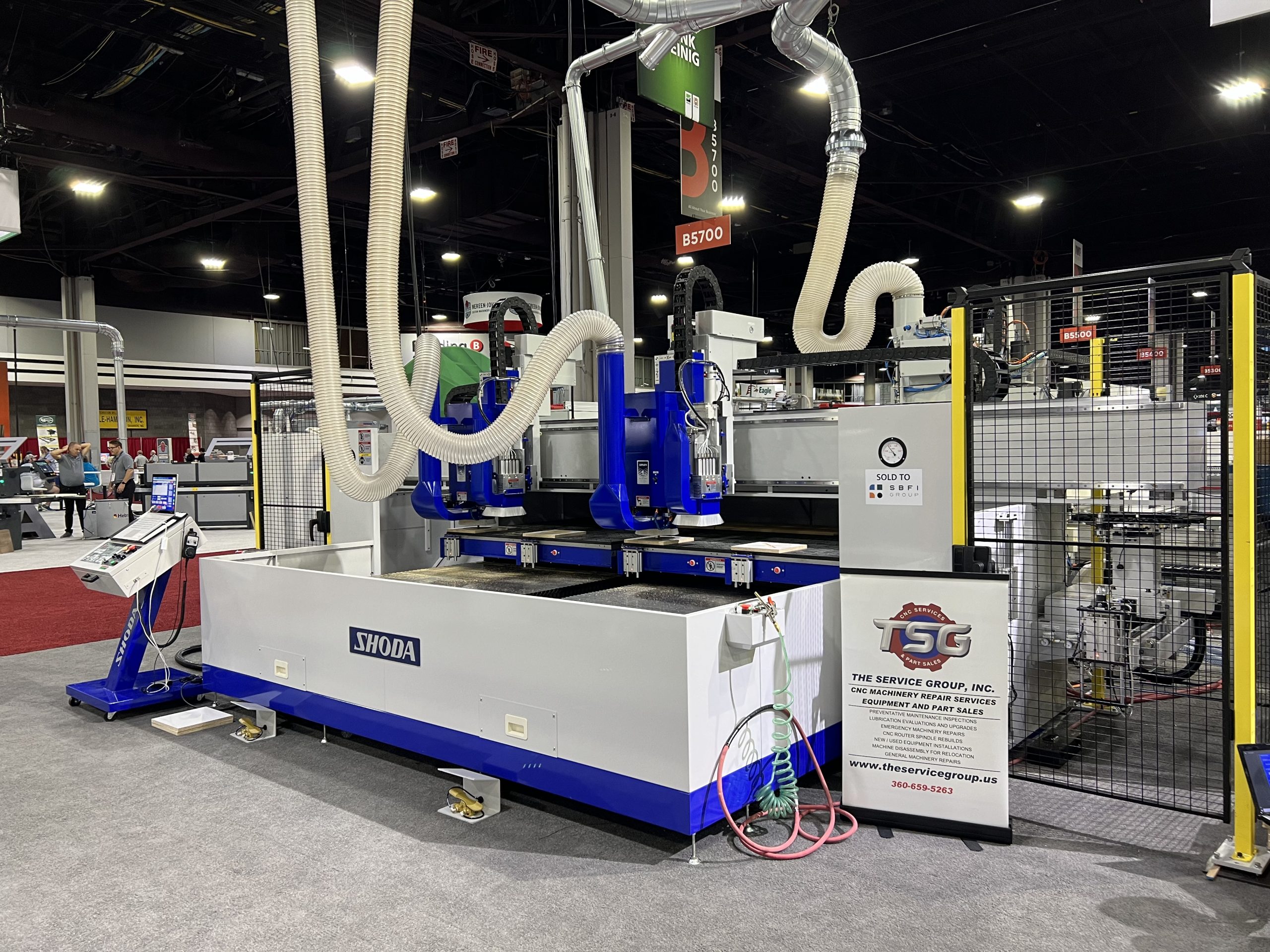
A Pioneer in Japanese CNC Router Technology
SHODA has been in business since 1926 and was the first company in Japan to develop an NC router. With a long history of precision machining, the company’s CNC routers are used to process a variety of materials—such as plastics, resins, and lightweight metals—with proven accuracy and reliability.
In 2014, SHODA developed a new type of NC router that doesn’t produce cutting dust. In many manufacturing environments, dust from machining can pose serious health risks if inhaled over long periods. SHODA’s solution to this issue has gained attention worldwide and is now used across the U.S., Europe, and Asia.